

High-Performance Steel Rule Die Bender Machine for Advanced Automatic Die Making
2026-08-27
In advanced automatic die making, precision and speed in steel rule bending can make or break your final cutting quality. If you're looking for equipment that handles high-performance demands without overcomplicating the workflow, ADEWO has a solution worth a closer look. Their steel rule die bender machine combines rugged construction with intelligent control, turning complex blade profiles into smooth, repeatable bends. This post explores how it helps packaging and printing manufacturers stay competitive in a fast-moving market.
Bending Steel Rules Without the Usual Trade-Offs
Steel has always demanded a choice: you could have a piece that bends easily or one that holds its shape under stress, but rarely both. Fabricators learned to accept thinning gauges, weaker welds, or brittle fractures as the cost of formability. These compromises filtered into every project, forcing designers to over-build or settle for less expressive shapes.
A different approach starts with the metallurgy itself. By refining grain structure and controlling the distribution of alloying elements, the material can flow into curves without developing micro-cracks that later become failure points. This means tight radii and complex profiles no longer require annealing steps that soften the final part. The steel keeps its load-bearing capacity even after repeated bending, so the same sheet can serve as both structural skin and decorative detail.
On the shop floor, this translates to fewer rejected parts and shorter lead times. Rollers and press brakes run at full speed without the usual test-bend calibration for each new batch. Welding distortion drops because the base metal stays uniform, not work-hardened in unpredictable spots. For architects and engineers, the real payoff is freedom: you can specify sweeping arcs and sharp folds in one component, knowing the steel won't punish the design for its ambition.
How Automation Removes the Guesswork From Die Making
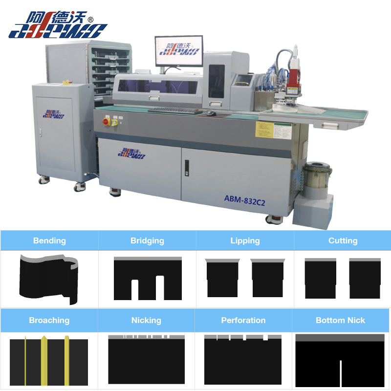
The guesswork in die making used to sit between the CAD model and the finished tool. Even with a perfect digital design, translating it into steel meant accounting for tool deflection, thermal growth, and material inconsistencies that no drawing fully captured. Automation bridges that gap by baking empirical rules into the toolpath and press cycle. Instead of a machinist manually reducing feed rate in a tight corner, the CAM system adjusts engagement angle, stepover, and spindle load in real time based on the actual cutter and steel being used. That takes away much of the feel-based adjustment that once separated an average die from a reliable one.
Closed-loop process control removes another layer of uncertainty. During tryout, force sensors in an automated press can detect when a blank is not flowing uniformly into a cavity. The system then shifts blank holder pressure or lubrication timing on the next stroke without anyone touching the machine. Rather than running five or six test parts, sectioning them, and adjusting by eye, the die reaches target dimensions in one or two cycles. This is not just faster; it prevents the small compounding errors that manual tweaks often introduced.
Simulation closes the remaining gap between prediction and reality. Automation lets a die maker test metal flow, springback, and stress distribution in software before any physical tool is built. When the simulated panel shows thinning above a set threshold, the die face or draw beads are revised digitally. By the time steel is cut, the major failure modes have already been designed away. The die maker still needs skill, but that skill now goes into reading simulation results and setting process windows, not chasing tenths of a millimeter with a hand grinder.
A Closer Look at the Cam-Driven Precision Path
A hardened groove cut into the side of a barrel cam does most of the thinking here. As the cam rotates, a pair of opposing rollers rides inside that groove, converting rotation into a linear sweep without the usual stack of linkages, belts, or servo corrections. The geometry of the groove itself sets the acceleration and dwell; nothing has to recalculate mid-move. That's what gives the motion its repeatable, almost mechanical certainty.
Backlash gets handled at the roller interface, not by tightening code. With two rollers preloaded against opposite walls of the groove, the assembly stays in contact through direction changes, so the output doesn't drift when the cam reverses. It's a small detail, but it removes the soft, mushy reversal you'd otherwise feel in cheaper setups. Over thousands of cycles, the path stays where it was cut.
The trade-off is that all the cleverness lives in the machining. Modify a dwell or change a stroke, and you're cutting a new cam rather than editing a parameter. For high-volume, fixed-sequence work, though, that's usually the point: the cam becomes the locked record of a motion you never have to tune again.
Handling Complex Profiles That Stop Older Machines
Legacy hardware often struggles when faced with intricate profile designs that demand more from the processor than it can comfortably deliver. These older machines, while reliable for straightforward tasks, can grind to a halt when asked to interpret complex curves, tight tolerances, or multi-axis movements embedded in a single profile. The issue is rarely the machine's physical capability but rather the way the profile data is structured—modern software tends to pack excessive detail into every instruction, assuming the controller can keep pace. When it cannot, the result is often stuttering motion, overheating, or outright failure to execute the program.
To keep these veterans running, the solution lies in simplifying the profile before it ever reaches the machine. Break down sweeping arcs into shorter linear segments that the control can digest without choking. Reduce the number of points in smooth regions where precision is less critical, and avoid nesting multiple coordinate transformations within a single move. Some operators also find success by lowering the feed rate override and letting the machine's own look-ahead function manage the heavy lifting, though this requires careful tuning to avoid introducing dwell marks. The goal is to translate the designer's intent into a language the old controller already speaks fluently.
Another effective workaround is to offload complex calculations to a separate pre-processor or a modern CAM station. By doing the heavy math away from the machine, the final G-code becomes a lean sequence of simple moves that older hardware can execute without hesitation. It's not about dumbing down the design; it's about respecting the machine's native rhythm and feeding it only what it can handle at its own pace. With this approach, even a 20-year-old mill can produce profiles that rival the output of far newer equipment.
Operator-Friendly Controls That Don’t Slow Production
The controls sit exactly where your hands already go. Twist the speed dial and it responds with a firm detent, no lag, no second-guessing. The few buttons that matter are raised just enough to find by touch while watching the workpiece. Nothing hides behind a touchscreen menu or a long-press shortcut. Operators learn the rhythm in a shift, not a training manual.
It is not about stripping features down; it is about placing them logically. Start, stop, jog, and feed override are clustered within a thumb’s reach. A gloved hand can tell the difference between them without looking. Adjustments happen mid-cycle without pausing the line, because the machine does not ask for confirmation screens or modal pop-ups. What used to be a three-step process now happens in one motion.
Production speed comes from eliminating hesitation. When an operator can change a parameter between parts and feel the machine respond immediately, there is no urge to work around the controls. The interface fades into the background, and the work itself stays front and center.
Building Dies That Hold Tolerance Run After Run
Every die maker knows the frustration of chasing micron-level drift between production runs. The real trick isn't hitting a tight number once—it's making that number boringly repeatable. Start by mapping your thermal growth cycles. A die that warms unevenly will always wander, no matter how rigid the frame looks on paper. Use tool steel with predictable expansion curves, and if you can, run a short warm-up batch before measuring critical features. The goal is to let the die settle into its working shape, then lock that shape into your inspection routine.
Wear patterns are the quiet killer of run-to-run consistency. Instead of waiting for parts to fall out of spec, track flank wear on cutting edges and build a schedule that replaces or re-sharpens before the slope gets steep. Many shops over-tighten the die structure thinking stiffness solves everything, but overly constrained setups often fight thermal movement and create unpredictable stress relief. A better approach is to design in controlled flex points—small reliefs that absorb expansion without shifting the working face. Pair that with a stable lubrication film, and you’ll see far less scatter in your measurements.
Finally, stop treating setup and teardown as separate from the die’s precision. Every clamp torque, every locating pin, every quick-release handle adds a variable. Document those numbers and train operators to hit them exactly, not approximately. The same goes for cleaning: residual chips or rust prevention goo can throw off seating by a few thousandths. Build a short, boring checklist that runs before every job, and your tolerance window stays put—run after run, without heroic effort.
FAQ
It handles standard steel rule from 0.71mm up to 2.0mm thickness, including coated and uncoated grades, as well as specialty profiles like serrated and perforating rules. The clamping and bending head are designed to prevent surface marking, which matters when working with pre-coated rules.
The machine reads CAD-generated bend programs and executes each angle in the exact order without manual re-clamping. This eliminates cumulative positioning error and lets a single operator hold tight tolerances across complex multi-up layouts, especially for packaging dies with intricate creasing channels.
Yes. The hydraulic system uses an oil cooler and a temperature-compensated bending cylinder, so angle drift stays under ±0.2 degrees even during continuous three-shift production. The steel frame is stress-relieved before machining to keep geometry stable over years of use.
It can produce sharp bends, radius bends from 0.4mm to 15mm, multiple height steps, and special profiles like Z-bends or bridge cuts. The software includes parametric macros for common packaging features like locking notches and slit-perforation transitions, reducing programming time from hours to minutes.
For flatbed dies it is the primary workhorse, but it also supports rotary die segments when paired with the optional cylindrical anvil attachment. The bending head can be offset to handle the different rule heights used in rotary applications, typically 0.5mm to 1.5mm above the base.
Most users are productive within two weeks. The controller uses a touchscreen with graphical preview of each bend, and the software flags impossible bend sequences before they run. A library of pre-tested templates for common carton styles shortens the learning curve considerably.
Daily checks are limited to air filter cleaning and checking hydraulic fluid level. Every 500 hours, the guide rails need re-greasing with a lithium-based lubricant, and the bending mandrel should be inspected for wear using a go/no-go gauge provided with the machine. No special tools are needed beyond a standard hex key set.
Conclusion
The High-Performance Steel Rule Die Bender Machine takes a different approach to rule bending by addressing the usual compromises head-on. Where older equipment forces a choice between speed, accuracy, and profile complexity, this system uses a cam-driven precision path that keeps the steel moving through the bend zone with constant support. Automation reads each rule profile and adjusts bend parameters without operator guesswork, so there is no need for repeated trial bends, hand shimming, or last-minute corrections. Tight radii, offset forms, and long production runs all hold the same geometry from the first part to the last.
The control side is built for real shop conditions. Operators get a clean, graphic interface with stored job libraries and one-touch recall, so changeovers stay short without limiting what the machine can do. Complex profiles that used to stall older machines now run in a single pass because the cam path and feed logic work together instead of fighting each other. That reliability carries into the finished die: cutting, creasing, and stripping stations stay aligned, and tolerance remains consistent run after run. In day-to-day use, the machine removes the guesswork from die making and lets a shop take on harder work without adding setup time or manual rework.
Contact Us
Contact Person: KAELYN LEE
Email: [email protected]
Tel/WhatsApp: +86 15012673758
Website: https://www.china-adewo.com