

HV Switchgear Factory: Inside the Precision Engineering Behind Modern Power Systems
2026-09-09
Most people never see the inside of a high-voltage switchgear factory, which is exactly why failures feel so sudden. At Chang Song, the factory floor tells a different story—one where precision assembly, laser-aligned contacts, and obsessive testing turn invisible components into the backbone of modern power grids. Here’s what really happens before the switch closes and the current flows.
Bending Copper Without Cracking: The Art of Busbar Forming
Copper busbar bending looks straightforward on paper, but the moment you push a thick bar past its natural radius, micro-tears start forming along the outer edge. The real trick isn’t brute force—it’s controlling strain distribution. Pure copper can stretch surprisingly far, yet work hardening from repeated bends or an overly tight die radius will concentrate stress until the surface simply gives way. Many experienced fabricators solve this by annealing only the bend zone with a soft flame, keeping the rest of the bar rigid enough to hold its shape. Get the temperature wrong, though, and you’re left with a soft, wobbly section that deforms under load.
Tooling choices matter just as much as heat. A sharp V-die creates a narrow plastic hinge, inviting cracks at the apex. A rotary-draw setup or a mandrel-assisted wipe bend spreads elongation over a wider arc, reducing peak strain. The ratio of bend radius to material thickness is the number to watch: most copper alloys used in busbar work can handle a radius of roughly one to one-and-a-half times the bar thickness without fracturing, provided the bend line runs perpendicular to the rolling direction. Rolling orients the grain, and bending with the grain is like snapping a wooden pencil along its fibers.
Even with good geometry, small details separate clean bends from scrap. A well-fitted internal support block prevents the inside face from collapsing into wrinkles that act as crack starters. A thin film of high-flash-point lubricant keeps friction heat from adding thermal stress to an already strained outer surface. Once these variables are dialed in, copper busbar forming becomes less about luck and more about repeatable judgment.
Inside the Vacuum Bottle: Where Contacts Meet for Milliseconds
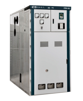
Inside the vacuum bottle, the real action happens in a space smaller than a coffee mug. When the contacts begin to separate, a metal vapor arc forms almost instantly, but the surrounding vacuum—typically at a pressure below 10⁻⁴ pascals—works against it. There's no gas to ionize and sustain the arc for long, so within a few milliseconds the arc loses its fuel. The contact gap becomes an insulator again, and current flow stops dead. That's the crucial window engineers obsess over: just long enough to break the circuit, yet short enough to avoid excessive contact wear or dangerous restrikes.
What often gets overlooked is the chaotic geometry of those milliseconds. As the movable contact pulls away, the arc doesn't just sit neatly between the two faces—it migrates, splits, and sometimes anchors to a single microscopic protrusion. Contact materials like copper-chromium are chosen because they vaporize unevenly under the arc, creating a diffuse plasma that spreads the heat instead of letting it drill a crater. The vacuum bottle's job is to let this dance play out, then swallow the debris. Within ten milliseconds, most of the vapor has re-condensed onto the shields and walls, leaving the gap clean enough to withstand the next voltage surge.
But milliseconds are relative. For a 50 Hz system, that's less than one half-cycle, meaning the bottle must interrupt current at a natural zero crossing or force a zero with a magnetic field. Some designs use spiral contacts to rotate the arc and keep it from lingering; others rely on axial fields to hold the arc diffuse and low-voltage. The entire mechanism depends on timing that no mechanical clock could manage—only the physics of vacuum itself, stripping away ionized particles as fast as they form. It's a stark, elegant act of subtraction, repeated thousands of times across decades of service, each interruption leaving the bottle just slightly older but not necessarily weaker.
Dry Rooms and Epoxy: Keeping Moisture Out of the Insulation
Moisture is the silent killer of electrical insulation. Even a fraction of a percent of water trapped inside winding layers can trigger partial discharges, accelerate thermal aging, and eventually lead to a short circuit. Dry rooms exist to strip that moisture away before the epoxy ever touches the copper. By holding the environment at a low relative humidity—often below 10%—and raising the temperature just enough to drive water out of porous materials, the insulation becomes genuinely dry, not just surface-dry. This step is not a formality; it is what separates a winding that lasts twenty years from one that fails in six months.
Once the components leave the dry room, the clock starts ticking. Dry insulation will eagerly reabsorb moisture from the ambient air if given the chance. That is where epoxy encapsulation becomes a two-part strategy. The resin does more than bond layers together—it forms a continuous, low-permeability barrier that locks out humidity for the life of the part. But the best epoxy in the world cannot fix moisture that was already there before mixing. This is why the dry room and the epoxy process are not separate steps; they are a single moisture-control system. Skip the dry room, and you are simply sealing water inside a nice plastic tomb.
In practice, winding shops measure the success of this marriage with a simple test: cut open a cured part and look for voids, then bake a sample and measure weight loss. Properly dried and epoxy-sealed insulation should lose almost nothing—maybe 0.05% by weight. That dryness translates directly into higher insulation resistance, lower dissipation factor, and a longer service life under voltage stress. It is not glamorous work, but it is the difference between a motor that runs quietly for decades and one that ends up as scrap after the first humid summer.
Laser-Guided Alignment on a 10-Ton Steel Frame
Positioning a 10-ton steel frame by eye is a losing game from the start. Even with a seasoned crew and heavy pry bars, the margin for error is measured in millimeters, and the consequences of being off can cascade through every downstream component. So we lean on a combination of machinist levels, precision targets, and a dual-axis laser system that gives us real-time displacement readings as the frame settles into place. The laser isn’t doing the lifting—it’s doing the arguing, turning a subjective “looks straight” into hard numbers that either confirm the placement or send us back to the shims.
On this particular frame, the anchor bolts were set in concrete days earlier, which meant our adjustment path was already partly locked in. The laser was mounted to a fixed reference point off the frame itself—usually a column line or an existing machine base—so that every shift of the structure was measured against something that couldn’t move. We worked in a sequence: first establish level across the top flanges, then bring the long edges into line, and only then check diagonal squareness. Each pass changed the previous reading slightly, so the process became a kind of slow negotiation, nudging one corner up by 0.4 mm while watching the opposing corner drift by 0.15 mm on the display.
The real value of laser guidance shows up after the frame is torqued down. Instead of hoping the tensioning didn’t pull things out of true, we run a final sweep across the critical mounting pads and record the deviation. On this job, the worst reading came in at 0.18 mm over a 9-meter span—well inside what the equipment manufacturer allows. That’s not a number you get from a plumb bob and a tight string. It comes from setting up a reference that doesn’t lie, and then being stubborn enough to keep adjusting until the frame agrees with it.
The Short-Circuit Test That Sounds Like Thunder Indoors
Walk into any high-voltage test bay and the first thing that hits you isn't the sight of the equipment—it's the pressure in the air. When a breaker fails its short-circuit test, the sound doesn't crack; it rolls. It starts as a metallic clap, then blooms into a low, chest-heavy boom that bounces off concrete walls until it feels like standing inside a thunderstorm. Technicians learn to read that noise the way sailors read a sky: a sharp snap means clean interruption, but a drawn-out rumble signals arcing that refused to die.
The test itself is brutally simple. You deliberately create a dead short on a circuit designed to handle thousands of amps, then tell the breaker to open. If it works, the fault current is chopped in milliseconds, leaving behind a smell of ozone and a copper busbar that's warm to the touch. If it fails, the room shakes. That's why the walls are lined with sound-absorbing panels and the control room sits behind double glass—not to protect your hearing, but to keep the blast from rattling your judgment.
Veteran engineers will tell you the thunder indoors is the only honest test. Datasheets and simulations can lie, but a breaker either breaks the arc or becomes the arc. When the last echo fades and the indicator light stays green, there's a collective exhale. The silence afterward feels louder than the noise itself, because it means the circuit is finally, truly dead until the next deliberate fault.
A Folder of X-Rays and Torque Logs Before the Crate Is Sealed
There’s a manila folder on the workbench, its top edge worn soft from being opened and closed all week. Inside are x-ray films clipped to torque logs, each sheet stamped with the same job number. The films show dark welds and lighter casting walls, a few circled shadows with a grease pencil note that says “accept — no crack at 6 o’clock.” The torque logs beside them list fastener locations, specified values, and two initials next to every line, some written in blue ink, some in black, depending on who handled that shift.
Before the crate lid goes down, the inspector pulls the folder out one more time. She checks the sequence numbers against the assembly order, flipping from an x-ray of a mounting boss to the torque sheet for the same area. One page has a corrected value, 82 N-m crossed out and 86 N-m written above it, with a brief note that a calibrated wrench was swapped in mid-run. The dates run in order, no gaps; the cover sheet has a stamp for final verification and a signature that is still slightly wet.
Then the folder goes into a clear polyethylene pouch taped inside the crate door. The corner of one x-ray sticks out a bit, and the inspector folds it back so it will not catch when the lid is pulled closed. The torque wrench is still on the bench, but its case is latched. Once the crate is sealed and banded, this folder becomes the only physical proof left of what got checked, and what got signed off, before the load left the floor.
FAQ
Every contact surface, insulating barrier, and bolt torque has to sit within incredibly tight tolerances. A tiny defect can turn into an arc fault under full load, so the whole process is built around eliminating variability.
It's not just a quick power-on check. Each unit faces lightning impulse tests, temperature rise runs, and partial discharge measurements. Some factories even X-ray busbar joints to catch hidden voids.
They need to understand electric field behavior and material limits. For example, the order and torque of bolt tightening directly affects contact resistance, and doing it wrong can create hot spots that only show up years later.
Copper busbar surface finish and contact alignment determine how much heat builds up at joints. A few microns of deviation can shorten equipment life, so precision machining is really the foundation of long-term performance.
Critical assembly areas run as positive pressure cleanrooms with tight humidity control. Some sensitive operations happen under nitrogen atmosphere to keep moisture away from insulation materials.
Many high-end factories offer witness testing and in-process inspections. Customer engineers can follow every critical step and even request additional factory acceptance tests beyond the standard routine.
Busbar insulation edge treatment. If edges are left slightly rough, corona discharge can develop over years of operation and eventually trigger a full insulation breakdown. It's a small detail with huge consequences.
Digital twins and live sensor monitoring allow engineers to simulate electrical performance before physical assembly. That cuts down rework dramatically and pushes first-pass yield rates much higher than old trial-and-error methods.
Conclusion
Walking through the HV switchgear plant, the first thing that strikes you is how much craft still hides inside industrial automation. Copper busbars are bent on CNC benders, but the real knowledge lives in tooling choices and bend radii that keep grain structure intact—no micro-cracks allowed, because a flawed busbar can turn into a hot spot under load. Nearby, vacuum interrupters are assembled in cleanrooms where contact faces are aligned to meet and separate within milliseconds. The vacuum bottle itself looks deceptively simple, yet it must quench an arc before it can build into a catastrophic failure. Down the hall, dry rooms hum constantly, holding air to desert-low dew points while workers mix and degas epoxy for insulation. Moisture intrusion here would mean partial discharge and slow death for a switchgear panel.
Precision tightens further when the 10-ton steel frame arrives. Laser trackers guide the alignment of breaker trucks, bushing plates, and earthing switches to tolerances that would make a machine shop nervous. Then comes the short-circuit test: the breaker closes into a bolted fault, and the lab erupts with a thunderclap that rattles your chest. Cameras and sensors capture arc duration, peak current, and contact wear in the same instant. Before any crate is sealed, a folder fills with X-ray images of critical welds and torque logs from every bolted joint. That paper trail is not bureaucratic—it is the only proof that this machine will sit quietly for years, then act decisively in the half-cycle when it matters most.
Contact Us
Contact Person: Tonglun Chen
Email: [email protected]
Tel/WhatsApp: 8618906642555
Website: https://www.cncsele.com