

OEM Swiss-Type Precision Parts Machining Factory Capabilities That Improve Complex Micro Component Quality
2026-11-18
Most micro component failures are decided long before final inspection—in how a Swiss-type machine is set up, how tools are managed, and how chips are kept away from delicate features. At WINNRUI CNC, those decisions are treated as core production capabilities, not afterthoughts. The result is a level of OEM precision that shows up in complex parts where tolerance stacking leaves no room for error. Here is a closer look at the factory capabilities behind that quality.
What Swiss-Type Turning Changes for Slender Micro Components
Slender micro components have always fought against deflection. On a conventional lathe, the cutting force pushes the workpiece away from the tool the moment the part extends more than a few diameters from the chuck. Swiss-type turning moves the support point directly behind the cut, so the bar stock never gets the chance to flex the way it would in a fixed-headstock setup. That single change is what makes diameter-to-length ratios that would otherwise chatter or bend become routine work.
The practical effect shows up most clearly in tolerances and surface finish. Because the guide bushing holds the stock within microns of the cutting edge, diameter variation along a 30 or 40 millimeter length often stays under a few tenths. Surface finish improves too, not because of higher spindle speeds alone, but because the tool is always cutting material that is mechanically stable. Secondary grinding or lapping steps can sometimes disappear from the process entirely.
There is also a less obvious shift in how shops handle the parts. When a 0.3 millimeter diameter pin no longer requires center support or tailstock contact, blanks can be fed continuously from bar stock. That reduces manual handling, but it also changes setup thinking: tool placement, chip control, and even spindle liner clearance become the variables that determine whether a micro part comes out straight.
The Guide Bushing Factor That Keeps Small Diameters Running True
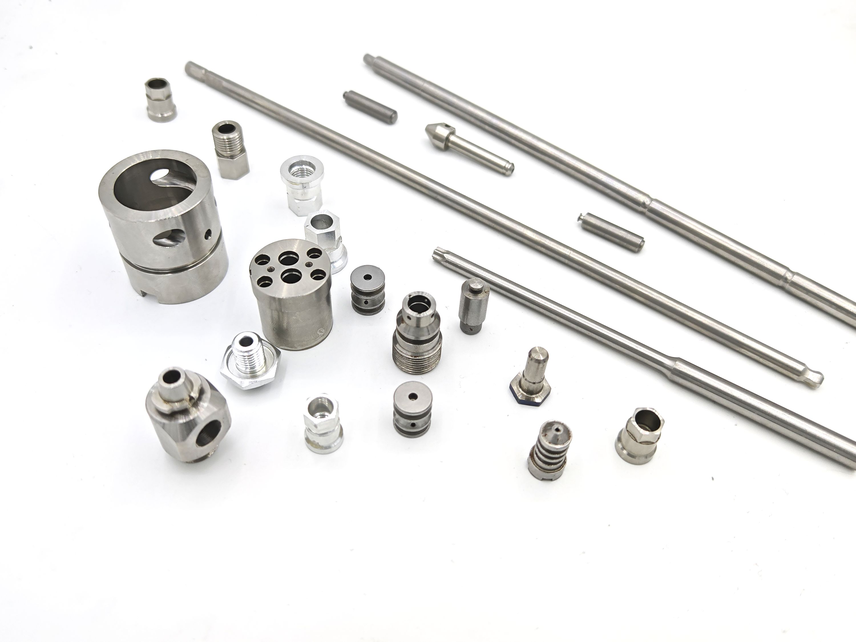
Small diameter turning often falls apart because the material flexes away from the tool, producing taper, chatter, and diameter drift. A guide bushing changes that by supporting the bar within a few millimeters of the cutting edge, so the unsupported length shrinks dramatically. On a 0.5 mm stainless steel pin, that close support can mean the difference between holding a two-micron tolerance and watching the part bend like a needle under load.
Clearance inside the bushing matters just as much as the support itself. Too tight, and thermal expansion seizes the bar or leaves score marks that ruin the finish. Too loose, and the tool starts chasing the workpiece instead of cutting it cleanly. Shops that keep small diameters running true usually check that clearance with a pin gauge, adjust for material growth during longer runs, and avoid letting chips pack into the gap where they can kick the bar off center.
The condition of the bushing also quietly sets the limit on roundness. A worn bore develops a slight bell mouth, which lets the bar drift in the exact spot where stiffness is needed most. Rotating guide bushings can help spread wear and reduce heat, while lined or carbide sleeves offer better life in abrasive materials. Regular inspection with a short test cut tends to reveal trouble before it shows up in inspection reports, especially when diameters drop below a few millimeters and there is no room left for corrective passes.
Micro Hole Drilling Without Wandering or Exit Burrs
A wandering micro drill almost always starts with the entry, not the hole itself. If the point contacts a rough surface, a slight radius, or even a hard spot at an angle, the web of the drill flexes and the tip walks before it finds center. Short, rigid drills with a split point help, but they are not a cure. A spot drill or a pilot hole that matches the micro drill's point angle removes the side load at entry and gives the cutting edges a clean cone to follow. On thin or unsupported sections, a machined flat or a center punch mark is rarely enough; the surface has to be prepared so the first contact is fully engaged with the material, not glancing across it.
Exit burrs are mostly a feed and support problem. When the drill approaches the back face, the remaining material becomes too thin to resist axial thrust and it bulges outward instead of being cut. Reducing feed only in the last few thousandths often works better than running slow all the way through, because it keeps the cutting edge shaving instead of pushing. A sacrificial backer clamped tightly against the exit side gives the material no room to deform. In production, backers made from aluminum or brass are common, but even a hard plastic can stop a small burr if the fit is tight and the drill breaks through into the backer instead of open air.
Toolholding and chip evacuation matter just as much as the drill itself. If the spindle has runout, the effective hole size grows and the drill cuts on one lip, which drifts the tip sideways and leaves an uneven exit. Hydraulic or shrink-fit holders with measured runout in the single-digit micron range keep the point centered. Pecking helps pull chips out of the hole, but too many pecks in a deep micro hole can create tiny dwell marks and make the exit more ragged. The best results usually come from a short, stiff setup, controlled runout, a low-feed exit, and a backer that catches the breakthrough.
Thermal Drift Control When a Few Microns Change Everything
A machine tool warms up unevenly. The spindle grows, the ball screws stretch, and the cast iron frame slowly bends under heat from motors and cutting friction. Over a full shift, these tiny expansions accumulate until the tool tip is no longer where the controller believes it is. Parts that measured perfectly at 9 a.m. can drift out of tolerance by early afternoon, even though nothing on the screen has changed.
Thermal drift control treats temperature not as a background condition but as a live variable in the positioning loop. Sensors embedded near the spindle bearings and guideways feed real-time offsets into the CNC, while algorithms learn how each axis responds to a given heat input. Some builders also run short warm-up cycles before precision work, not to exercise the machine, but to bring it to a stable thermal state where drift slows to a manageable crawl.
The payoff shows up in processes where a few microns separate a good part from scrap, such as fine boring, grinding, or electrode production. Shops that once measured parts twice and still argued over borderline results now hold dimensions through lunch breaks and seasonal temperature swings. The machine still moves thermally; it just no longer lies about where it is.
Deburring Without Reshaping the Micro Geometry You Just Cut
Removing a burr without touching the surrounding edges is harder than it sounds, especially when the part carries micro geometry that took careful toolpath work to produce. A stiff wire wheel or an aggressive tumbling cycle will knock the burr off, but it also dulls the very intersections and land widths you need to keep sharp. The practical approach is to treat deburring as a separate, tightly controlled step rather than a quick clean-up. That often means using a small-diameter brush with the pressure mapped in CAM, or switching to a non-contact method when the feature is too fragile to risk any mechanical contact.
The key is to preserve the cut surface as the reference. If the deburring tool is allowed to ride along the edge, it should follow the original toolpath logic instead of being driven by a constant force that can wander into the profile. In many shops this is done by programming the deburring pass from the same geometry that drove the finishing cutter, then running at lower speed with a controlled offset. It removes the thin, weakened material at the edge while leaving the form below it untouched, which matters when the micro geometry is functional rather than cosmetic.
Some materials respond better to methods that do not rely on edge contact at all. Thermal and electrochemical deburring can dissolve or lift the burr without loading the part the way a brush does, and they are often chosen when the burr sits inside an intersection or along a thin wall where even a light touch would push the feature out of tolerance. Whatever method is used, the result should be checked against the pre-deburr edge condition, not just for remaining burrs but for any rounding that crept in. If the edge still reads the same after the process, the deburring step did its job without erasing the geometry it was meant to protect.
Inspection Practices That Catch What Drawings Only Imply
Drawings often give a dimension but not the entire story behind it. A hole callout may show position and size, yet the real requirement is that a mating pin drops through without binding under assembly loads. Inspectors who stop at the print can pass a part that still fails on the line. Catching what is implied means checking fit under realistic conditions instead of only verifying numbers. Use functional gages, stack components in the order they are built, and ask whether the tolerance zone actually protects the intended function.
Surface finish and edge condition are two places where prints tend to stay quiet. A corner can meet every burr note and still slice a seal or snag a wire harness later. That shifts inspection from instruments to touch and context. Run a gloved finger along edges, slide a mating part over the surface, or view it under low-angle light. The aim is not to invent hidden requirements but to recognize that the drawing assumes a level of workmanship no general note fully captures.
Another habit that separates useful inspection from box-checking is walking the part through the next operation before a batch leaves the floor. If a bore needs to align after welding, check it with the same clamps and torque. If a coating thickness is called out, confirm it on the surfaces that actually contact another part, not just on a flat coupon. These checks catch mismatches that are never stated outright but become obvious the moment parts meet.
FAQ
The bar stock is fed through a sliding headstock and supported by a guide bushing right next to the cutting zone. That local support keeps slender parts from flexing, so features stay concentric and stable even when length-to-diameter ratios get extreme.
Long slender geometries tend to deflect under tool pressure once the material extends beyond the chuck. Swiss-type machines support the bar near the cutting edge, which reduces vibration and lets the tool handle small diameters, deep cuts, and tight length-to-diameter ratios without losing form.
Look for in-house setup on sliding headstock machines with sub-spindles, high-pressure coolant through the tool, and live tooling. That combination allows roughing, finish turning, milling, drilling, and back-working in one cycle, so the part does not need to be re-fixtured between operations.
Once the main spindle finishes the front features, the sub-spindle grabs the part and the machine cuts the back side without removing it from the setup. This eliminates alignment errors from secondary clamping and keeps total runout and concentricity much tighter than separate operations would.
Yes, but the setup and tooling have to be right. Small carbide drills, proper peck cycles, controlled feed rates, and high-pressure coolant help clear chips from deep micro holes. For thin walls, sharp tools and light finishing passes are used to avoid pushing the material around.
Many shops routinely hold tolerances in the plus or minus 0.005 mm to 0.01 mm range on key diameters and lengths, depending on geometry and material. The more critical dimensions are often validated with optical measurement or touch probes rather than hand gauges.
The process is adjusted around the alloy. Stainless steel, titanium, and nickel alloys usually require slower surface speeds, rigid tool holders, specialized coatings, and high-pressure coolant. The guide bushing setup helps reduce chatter, but stable chip control is the main challenge.
Discuss minimum wall thickness, thread class, surface finish callouts, burr allowances, and how the part will be fed in automated assembly. Small changes like adding a relief groove or adjusting a corner radius can make the part easier to machine and more consistent in production.
Conclusion
The real advantage of an OEM Swiss-type precision parts machining factory shows up on slender micro components. A Swiss-type lathe changes the way these parts are cut because the material feeds through a guide bushing right at the tool zone. That support keeps a 0.5 mm diameter from flexing or chattering, so the turned profile stays round and the surface finish does not drift from one end of the bar to the other. When the same part needs a 0.2 mm hole, the tool path and peck cycle are set to prevent the drill from walking off center, and the exit side is controlled well enough to avoid the ragged burr that would later cause fit or flow problems. Thermal drift gets the same attention as tool wear: spindle warm-up, coolant temperature, and cutting loads are kept within a narrow band because a few microns of growth can erase the tolerance on a tiny sealing face.
After machining, deburring is handled with techniques that remove only the loose edge without rounding a sharp seat or altering a critical bore entrance. Inspection goes beyond checking the dimensions that appear on the print. Straightness, edge condition, and residual burr height are measured because drawings often imply those requirements without giving a number. The result is a part that assembles predictably and performs consistently in a complex device, not just a part that passes a basic dimensional check.
Contact Us
Contact Person: Tim
Email: [email protected]
Tel/WhatsApp: +86 15522553731
Website: https://www.winnrui-cnc.com/