

Top 10 Video Measuring Machines for Accurate Dimensional Inspection
2026-10-01
Dimensional inspection is where good parts become certifiable parts—and where sloppy measurement quietly eats your margin. In this list, we skip the spec-sheet theater and focus on video measuring machines that hold tolerance when it counts. Keep an eye out for JATEN, a brand that's been turning heads for all the right reasons.
Why Two Machines with the Same Specs Can Measure Differently
Identical specifications on paper don't guarantee identical readings in practice. The most common culprit is subtle variation in calibration—each machine leaves the factory with its own slight offset in sensors, load cells, or optical encoders, and unless both units are recalibrated against the same traceable standard right before testing, those small biases accumulate into noticeable differences.
Environmental factors also play a bigger role than many assume. Temperature swings can expand or contract critical components, humidity affects electrical resistance and optical clarity, and even minute differences in benchtop vibration or air currents can skew sensitive measurements. Two machines sitting side by side in the same lab may still experience slightly different microclimates due to airflow from a vent, proximity to a heat source, or the operator's own body heat.
Finally, the human element introduces variability that specs can't capture. How firmly a sample is seated, the exact alignment of a probe, the speed at which a fixture is tightened, or even the order in which measurements are taken can all shift results. One technician may consistently apply slightly more torque than another, or use a different technique when zeroing the instrument. These procedural differences, repeated over dozens of measurements, create a pattern of divergence that has nothing to do with the hardware itself.
The Quiet Work of Telecentric Lenses and Ring Lights
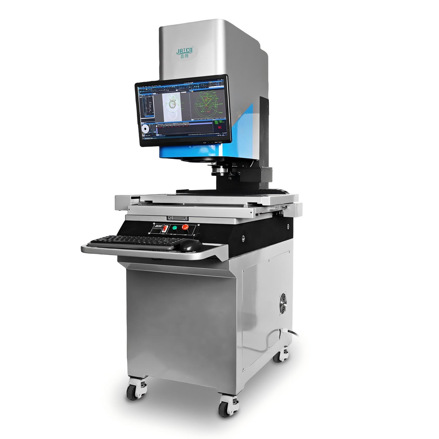
Inspection stations rarely get much attention when everything runs smoothly. That's exactly where telecentric lenses and ring lights earn their keep—not through flashy specs, but through a kind of silent reliability. A telecentric lens removes perspective error, so a part that sits a millimeter closer to the camera doesn't suddenly appear larger than an identical part a millimeter farther away. Pair that with a ring light mounted around the lens, and you get illumination that hugs the optical axis, eliminating harsh shadows on edges or recessed features. The result is a measurement image that stays consistent hour after hour, batch after batch.
What makes this pairing so effective for precision work is how it handles the small, stubborn problems. Reflective surfaces, tiny holes, threaded profiles—these are the details that cause ordinary setups to drift out of tolerance. A telecentric lens keeps the field of view flat and orthographic, so cylindrical objects are measured by their true diameter rather than a distorted outline. The ring light, with its evenly spaced LEDs, wraps around the part without creating hot spots or uneven glare. It's a quiet collaboration: the lens defines the geometry, and the light reveals the texture, all without demanding constant recalibration.
Many machine vision guides focus on resolution charts or lighting diagrams, but the real value often shows up during a late shift when the line keeps running without an operator hovering nearby. Telecentric lenses and ring lights don't need to be told to behave—they simply work within their design limits. For anyone building a robust measurement cell, choosing this combination isn't a dramatic decision; it's more like selecting a good pair of calipers. You forget they're there, and that's the point. The images stay true, the edges stay crisp, and the numbers on the screen remain trustworthy long after the setup has been forgotten.
Thin-Walled Parts, Micro Holes, and Other Cases That Break Contact Probing
Thin-walled parts deflect under even light stylus pressure. A probe tip that triggers at a few millinewtons can still push a 0.5 mm aluminum wall out of position by several microns, so the recorded coordinate belongs to a temporarily bent surface, not the free-state geometry. The error is often repeatable enough to pass a GR&R study, which makes it harder to spot.
Micro holes below about 0.3 mm create a related but different failure. The stylus ball either cannot enter without scraping the edges or, if it does fit, any slight misalignment turns the hole into a tiny lever that magnifies side forces. Chipped carbide edges and rounded hole rims from repeated touchdowns are common, and the probe may report a center point that has drifted from the actual axis.
Other cases include soft polymers, thin coatings, and freshly machined surfaces where contact probing leaves witness marks or changes local stress. In these situations, non-contact methods such as vision systems or chromatic confocal sensors tend to be used, but they come with their own trade-offs in reflectivity and edge definition. The common thread is that the measurement act itself alters the part enough to undermine the number.
From Point Cloud to Pass/Fail: What the Software Is Actually Doing
Most inspection software starts with a raw point cloud—millions of individual measurements captured by a scanner. That data looks like a fuzzy digital sculpture, full of noise and gaps. The software doesn't see a part yet; it sees coordinates. So the first real job is making sense of that mess. It filters out stray points, aligns the cloud to a known reference frame, and stitches multiple scans into a single coherent surface. Only then can it start comparing what's there against what should be there.
The next stage is where the magic happens: deviation analysis. The software overlays the measured point cloud onto the nominal CAD model and calculates the distance between every point and the ideal surface. Those distances get color-mapped—green for within tolerance, red for out of spec, blue for interference. But color maps are just pictures. A good inspection tool goes further, extracting geometric features like hole diameters, flatness, and profile tolerances, then checking each one against the drawing's GD&T callouts. That's the difference between a pretty visualization and a pass/fail decision.
Finally, the software compiles all those individual checks into a report. It flags dimensions that are drifting toward their limits, highlights surfaces that show unexpected deformation, and sometimes even suggests likely manufacturing causes. The operator doesn't have to interpret a hundred color gradients—they get a clear statement: this part meets spec, or these five features failed. Modern packages can even learn from past inspection runs, adjusting pass thresholds to match actual process capability. That's the full journey: millions of raw points, a few seconds of computation, and one answer.
Granite, Air Bearings, and the Fight Against Thermal Drift
Granite has earned its place in high-precision stages not because it is merely heavy, but because its thermal expansion is low enough to serve as a dimensional anchor. In a well-designed system, the granite beam or base plate resists the slow creep of room-temperature changes long enough for active compensation to do its work. The material’s internal damping also keeps high-frequency vibration from turning into position noise, which matters when air bearings remove the friction that would otherwise mask those errors.
Air bearings, for their part, introduce a subtle complication. The thin film of compressed air that separates moving and stationary surfaces is typically 5 to 10 micrometers thick, and its stiffness changes with temperature and supply pressure. As the air warms, its viscosity shifts, and the bearing gap changes fractionally. That gap is effectively part of the metrology loop, so a temperature rise of a few degrees can show up as a few hundred nanometers of vertical drift. No amount of preload can fully eliminate this; it has to be measured and compensated.
The real fight against thermal drift happens at the system level. Machine builders mix passive tactics—long thermal time constants from granite, shielding from heat sources, symmetric structures—with active correction from distributed temperature sensors and real-time error maps. The hardest problems are transient: when a stage moves, it drags a thermal wake through the air film and across the granite. Solving that requires understanding where the heat actually goes, not just what the average temperature is.
Before You Buy: Run a Gauge R&R, Not Just a Demo
A demo is staged to make the gage look effortless: clean parts, one highly practiced operator, and a temperature-controlled lab. Your shop floor has none of that. Real parts carry burrs, coolant residue, and enough dimensional variation to stress the entire measurement loop. If a salesperson hands you a stack of perfect repeatability charts, ask which shift ran those parts and how many operators were involved.
Before signing a purchase order, run a Gauge R&R on your own parts, with your own people, under your normal conditions. Use at least two or three operators, ten parts that span the actual tolerance range, and two or three randomized trials per part. Then look at the percent GRR and the number of distinct categories. If percent GRR comes back above 30 percent or ndc drops below 5, that instrument cannot tell the difference between good and bad parts on your line.
A pre-purchase Gauge R&R costs a day of time, but it converts marketing claims into decision-ready data. If the study fails, you walk away before the invoice arrives. If it passes, you buy with evidence that the gage adds value to every acceptance call, not just the ones made in the demo room.
FAQ
Focus on the optical system and lighting control. A zoom lens with a high numerical aperture can resolve smaller features, but without programmable ring light or coaxial illumination, you'll struggle to get repeatable edge detection on textured surfaces. Test with your own part, not just a calibration grid.
Travel is the distance the stage can physically move, but the actual measurable volume depends on working distance and Z-axis range. Many buyers overspend on X-Y travel while ignoring Z clearance. If you're measuring tall molded housings, a long-working-distance lens and high Z travel will matter more than an extra 50 mm of table length.
Only if they specify the standard used, like ISO 10360 or a similar acceptance test. A bare E2 = 1.5 + 3L/1000 µm without temperature range or probing method is incomplete. Ask for a certified test report with your part geometry, not just a laser interferometer check under ideal lab conditions.
Yes, that is one of its strengths. Non-contact optical measurement avoids deforming rubber gaskets, thin films, or delicate PCB sections. However, translucent or highly reflective materials can cause false edge readings unless you adjust illumination angles or use polarizing filters.
More than the hardware in many cases. Look for offline programming so you can prepare measurement routines without tying up the machine. Features like auto edge detection, CAD import, and geometric dimensioning and tolerancing reporting save time, but only if the interface is not buried in menus. A quick routine change on the floor should not require a call to the vendor.
It depends on usage and environment. In a temperature-stable room with moderate use, an annual verification is common. If the machine sits near a loading dock or runs three shifts, quarterly checks are safer. At minimum, verify scale accuracy with a traceable glass scale every few months and recalibrate after any crash or stage rebuild.
The difference usually lies in the frame rigidity, bearing quality, and thermal compensation. A cheaper granito base may flex more under heavy stages, causing repeatability drift. Premium machines often include active temperature compensation and servo motors that settle faster. For long-term reproducibility, those hidden components matter more than the camera resolution listed in the spec sheet.
Use the correct lighting mode and, if available, a surface-tracking autofocus. For angled edges, backlighting may create shadow ambiguity, so a ring light at low angle or a coaxial light helps. If the surface is steeply curved, consider a rotary stage or 3D sensor add-on. Taking multiple Z-slice images and stitching them can also reduce uncertainty.
Conclusion
Selecting among ten capable video measuring machines goes far beyond reading a specification sheet. Two systems with identical resolution and accuracy ratings can still produce different numbers on the same part because of subtle differences in stage build, lighting calibration, and how the software interprets image contrast. That is why telecentric lenses and properly positioned ring lights deserve more attention than they usually get. A telecentric setup removes perspective error so edges stay sharp regardless of part height, while a well-tuned ring light suppresses shadows and highlights the true boundary. For thin-walled components, micro holes, or easily deformed plastic features, non-contact video measurement is often the only practical route; a touch probe would push the surface out of position or simply miss a 0.1 mm hole altogether.
Behind the camera, the software does more than just collect points. It filters noise, fits geometric primitives like circles and planes, and turns a noisy point cloud into a repeatable pass/fail call. This step can hide weakness in the hardware or expose it, so buyers should not be impressed by a quick demo on an ideal part. The mechanical foundation matters just as much: granite bases, air bearings, and thermal compensation work quietly to keep measurements stable as the room temperature shifts. Before committing, run a gauge repeatability and reproducibility study on your own parts, with multiple operators and several measurement loops. That test reveals whether the machine is truly consistent enough for your tolerances, not just whether it looks good in a brochure.
Contact Us
Contact Person: Volien
Email: [email protected]
Tel/WhatsApp: +86 18029161762
Website: https://www.jatentech.com/